Introduction
This page covers the Heusinkveld Sim Pedals Ultimate+ in the colour black and contains extra information which is not in the quick start manual. We advise you to read this page thoroughly in order to get the most enjoyment out of your pedal set.
Initial setup
In this section we will get your Sim Pedals Ultimate+ up and running. Detailed software and mechanical adjustments are explained later in this manual.
Mounting the pedals
The base of each pedal has 4 mounting slots. The maximum bolt size for these slots is M6 (6 millimeter). Possible mounting solutions are 80/20 aluminium beams, a Heusinkveld Baseplate or several available third party rigs or mounting plates.
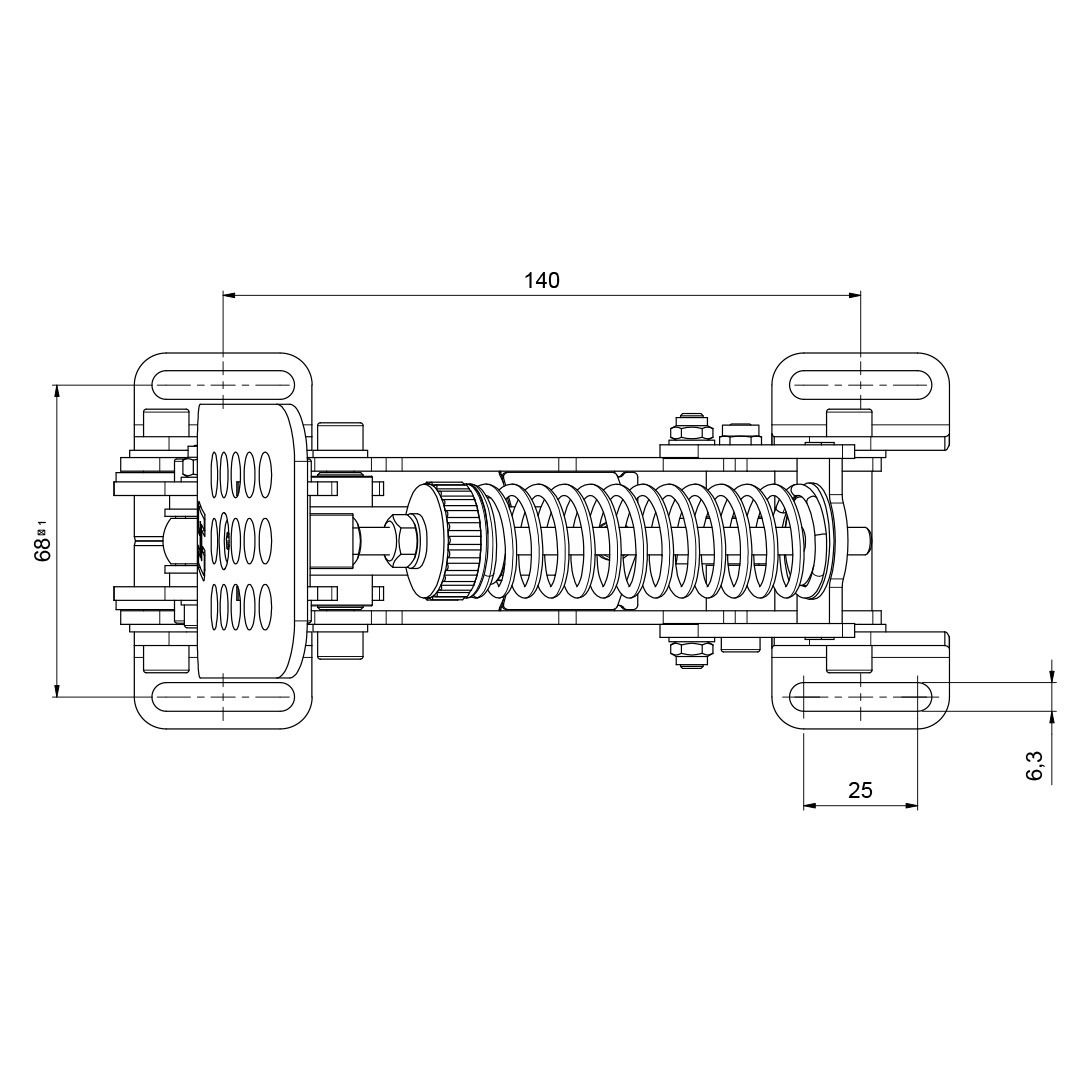
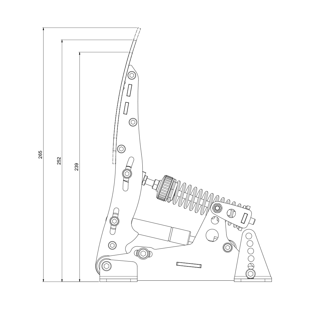
Keep in mind that the Sim Pedals Ultimate+ may be loaded with 140kgs at the brake pedal, when applying these loads you must install the pedals on a very rigid base. See the image for the base and profile dimemsions of the Sim Pedals. All dimensions are in millimeters unless stated otherwise.
Installing the electronics
Each pedal needs to be connected to the USB-controller which is included with your pedal set. The controller is the small box with the metal enclosure with the text ‘Sim Pedals Ultimate+ SmartControl’ printed on top.
Every pedal has a wire with an RJ-plug at the end. Your Sim Pedals Ultimate+ are pre-calibrated. Because of this you need to insert the RJ-plug of each pedal in the correct port on the controller. The ports on the controller are labelled. If you have a 2-pedal set without clutch, you can leave the clutch port empty.
Next, connect the provided USB-cable. One side of the cable can be plugged into the controller. The other side should be connected directly to your pc.
Please make sure there always is a bit of slack in the cables. This prevents damage to plugs, sockets and electronics. Specifically if you use a motion simulator, secure the USB cable to the (moving) frame of your simulator before you connect it to the controller.
-
 Throttle pedal
 -
 Brake pedal
 -
 Clutch pedal
 -
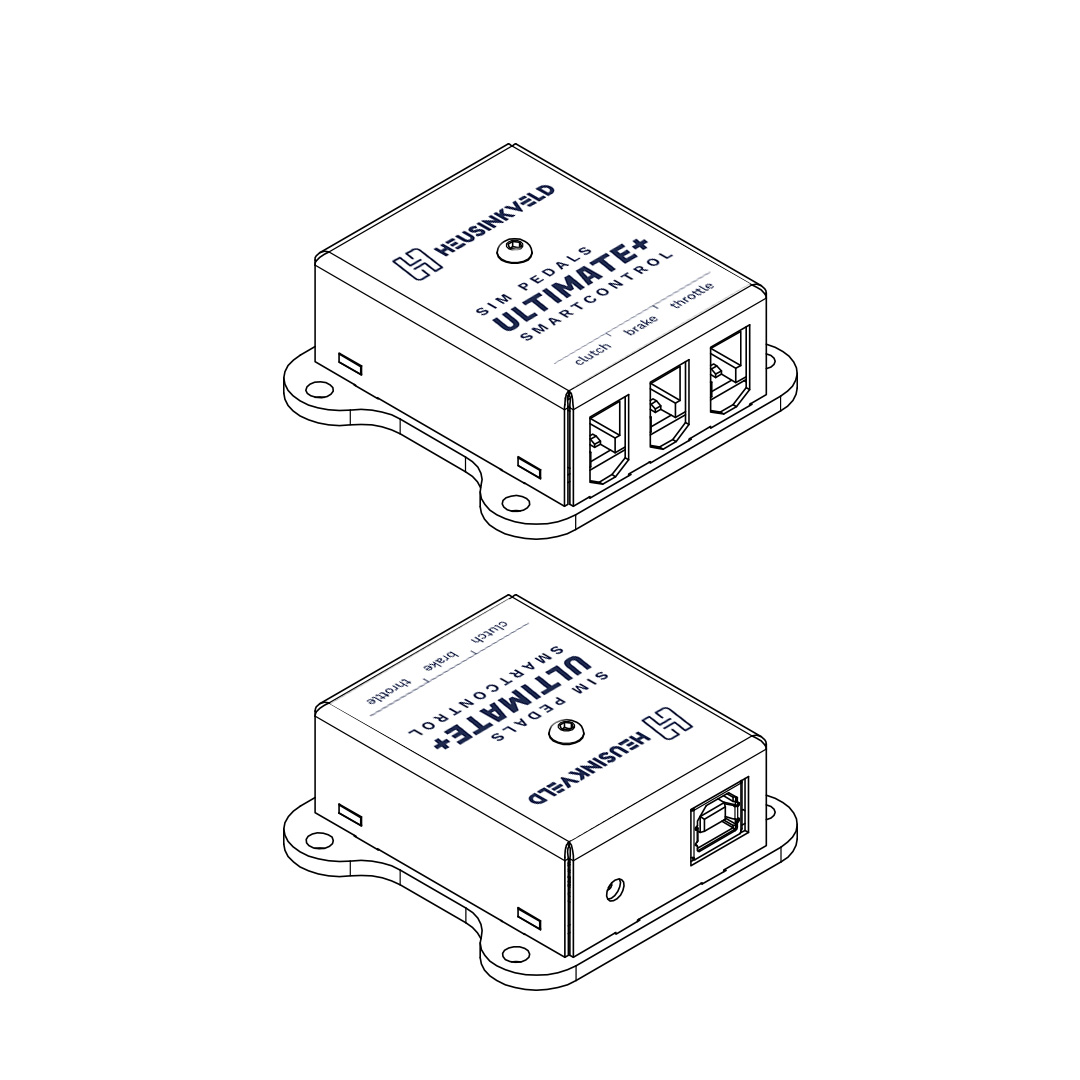 USB-Controller box
Plug & play
Your pedals are now ready for racing. They are pre-calibrated with a brake force of appr. 80kg and will work after assigning them in your favourite simulator software. Please note that iRacing requires an additional one-time in-game calibration: calibrate all axis to an output of 4095.
SmartControl adjustments
Your Sim Pedals Sprint come with a powerful configuration tool allowing you to set up your pedals in ways not previously possible: SmartControl.
Download SmartControl & SmartControl Live
SmartControl & SmartControl Live software can be downloaded here.
Short overview
With SmartControl you can configure (non-linear) pedal output curves, set pedal deadzones and the brake pedal force. All settings can be saved into profiles, which can be loaded again in a few mouse clicks.
Settings applied in SmartControl will have effect in any simulator software, without having to make additional adjustments, re-assign controls or recalibrate (including iRacing) in the simulator software itself.
SmartControl LIVE is a software service which is designed to run in the background while using your simulator. It allows you to switch between profiles created using SmartControl while driving. It also allows you to set the required brake force of your brake pedal or handbrake on the fly.
For a more extensive overview of SmartControl & SmartControl Live features please click here. [LINK]
Calibration
SmartControl also includes a calibration wizard. Because your pedals have been pre-calibrated during assembly, calibration is not required before first use. Recalibration in SmartControl is only required when:
- The mechanical end-stop of the throttle pedal has been adjusted.
- Mechanical adjustments have been made to the brake.
- The cables of the throttle and clutch pedal have been switched in the brake-mounted controller (for example when you mount your pedals inverted).
Throttle and clutch deadzone adjustment
For the throttle and clutch pedal you can set a bottom and top deadzone in SmartControl.
- Bottom deadzone: Pedal output starts after a little bit of movement from the pedal.
- Top deadzone: Pedal output reaches 100% a little bit before hitting the endstop.
The throttle and clutch deadzone are expressed as a percentage of total pedal travel. The effect of your deadzone setting can be checked in realtime in the green vertical signal output bar.
Because the Ultimate+ use relatively soft endstops there may be small signal variations between instances of the pedal being at rest or being fully pressed. We therefore always recommend setting a minimum bottom & top deadzone of 3%. You should get 0% or 100% pedal output without having to force the pedals into their endstop.
Especially on the clutch pedal a larger top deadzone will influence the bite point, the point where releasing the clutch further makes the car move. This depends greatly on the software title and car used. A larger bottom deadzone will prevent accidental clutch slip from resting your foot on the pedal.
Brake bottom deadzone adjustment
Preload on the rubber stack applies a small force to the load cell. After SmartControl calibration, this slight initial force becomes 0% output. The bottom deadzone can apply additional offset, resulting in a brake pedal that needs some initial force and movement before becoming active.
The bottom deadzone is a percentage of the set brake force. At 60kg brake force and 5% deadzone, the load cell will register 3 kg of force before brake pedal output starts. The effect of your deadzone setting can be checked in realtime in the green vertical signal output bar.
Your brake is equipped with a 2-stage system. Initially a metal coil spring is compressed. This coil spring simulates the pad-to-disc gap. The main loading of the brake disc is simulated by compressing the rubbers. A use case for setting a large bottom deadzone can be that you only want braking in the simulator to start after the metal coil spring has been fully compressed.
Brake force setting
SmartControl allows you to set a maximum force on the brake pedal. This setting is in kilograms (kg) and represents the actual brake force where your foot touches the brake pedal pad (for a medium sized foot).
When you press the set maximum force on the brake pedal, the pedal will give 100% brake output signal to the simulator software. The maximum brake force of the Ultimate+ pedals is 140kg with the hard elastomers and 100kg when using soft elastmers.
How you set the maximum brake force depends on your personal preference. Even in similar real race cars, the required peak brake force varies a lot as this is a function of the size of the brake cylinders and other components installed in that specific car.
In general, fast high-downforce race cars require higher brake forces than slower, low-downforce race cars.
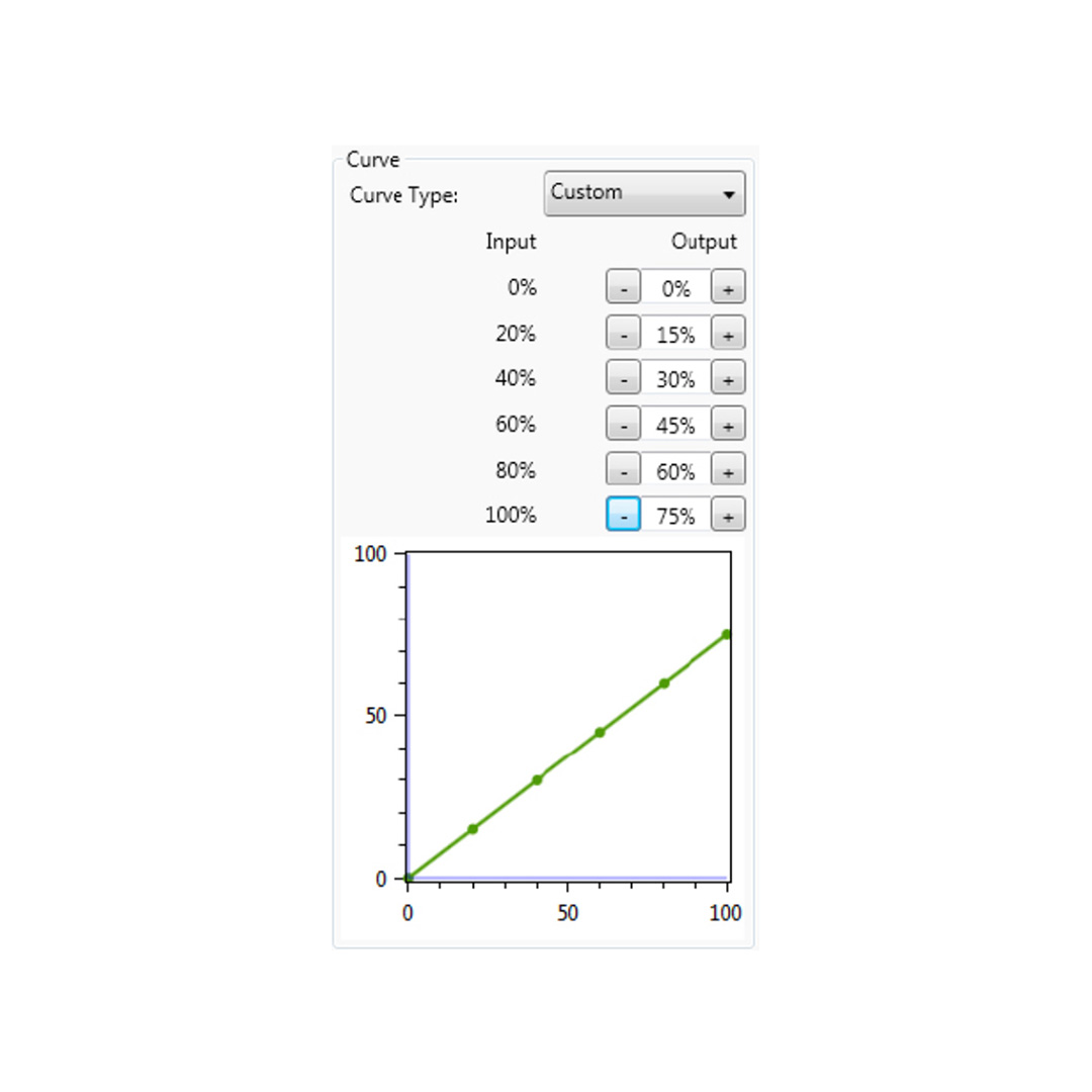
A key feature of SmartControl is the ability to set custom signal output maps per pedal. Traditionally race simulator pedal output has had a one-on-one sensitivity in relation to the pedal input. SmartControl allows you to map non-linear output curves using 5 zones (six input parameters).
Each pedal has a Curve Type pull-down menu with pre-defined output curves. Here you can also select the option to make a custom curve and then set the desired pedal output percentage at the 0%, 20%, 40%, 60%, 80% and 100% marks of the pedal input. You have complete freedom to set your own shapes.
Please note that some simulator software offers in-game options affecting the linearity of certain pedal outputs. In order for SmartControl to work effectively, always make sure that all in-game pedal settings are set to linear.
We will illustrate this functionality with a few use cases.
Use case 1: Throttle curve in case of rain
Real race car drivers have the option to adjust the throttle response of their car to be less sensitive on initial input. This helps to prevent unintended wheelspin when starting to apply the throttle in slippery conditions, such as rain. SmartControl allows you to set a lower sensitivity in the early phases of throttle application.
-
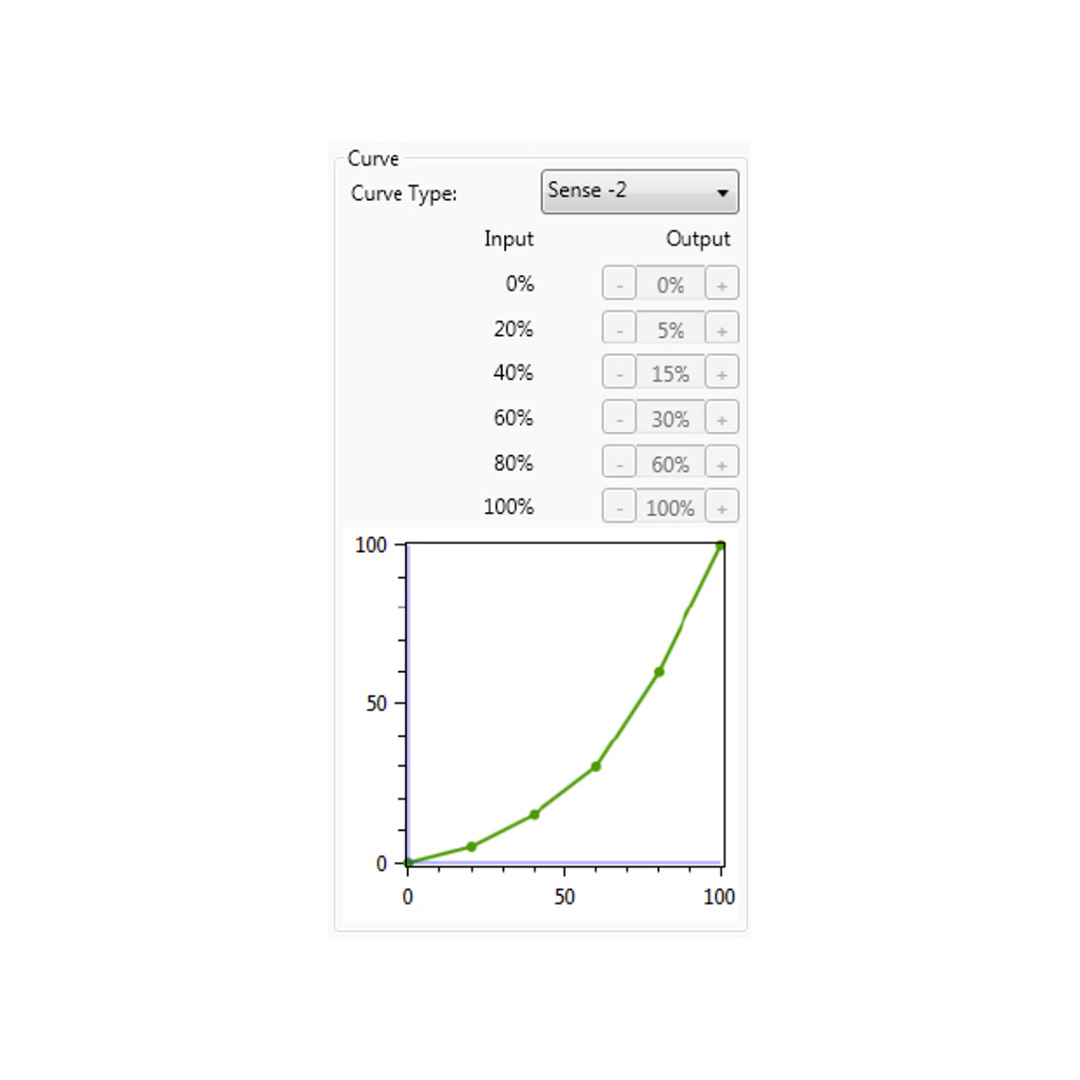 Use case 1 Throttle curve in case of rain
Use case 2: Throttle curve in an underpowered car
As opposed to use case 1, sometimes you want your throttle response to be as aggressive as possible. This can be the case when you race an underpowered car with limited chance of wheelspin. SmartControl allows you to set a curve in which the sensitivity is higher in the initial phases of throttle application.
-
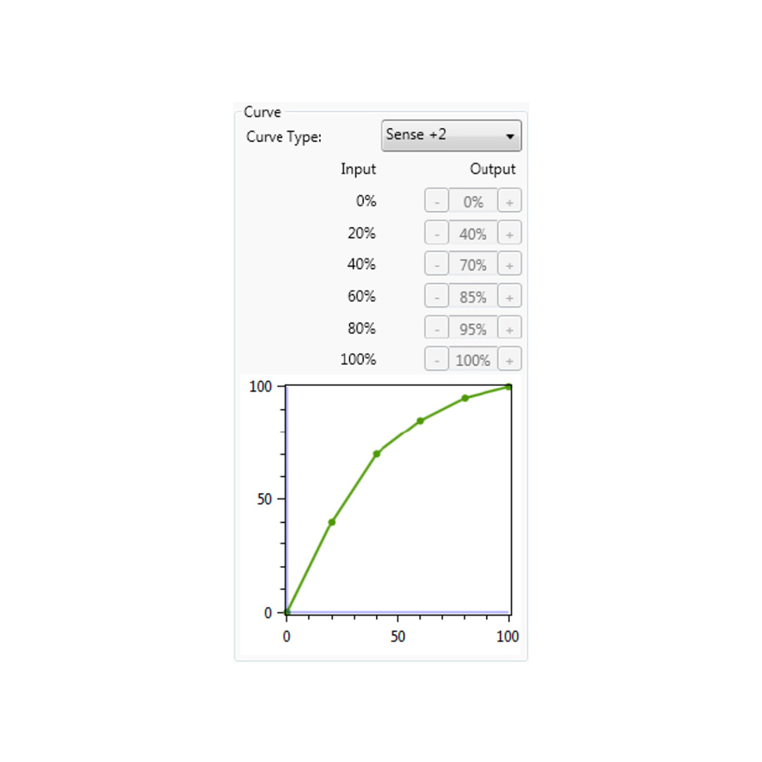 Use case 2 Throttle curve in an underpowered car
Use case 3: Clutch curve with optimal bite point setting
When making a standing start, you want to reach an optimal ratio between clutch slip and RPM. This ensures you have maximum acceleration.
If you know where this optimal bite point of your clutch is, you can configure the clutch output curve in a way that it is easy to accurately reach and hold the optimal bite-point. In the image the optimal bite point is when the clutch is 50% disengaged.
-
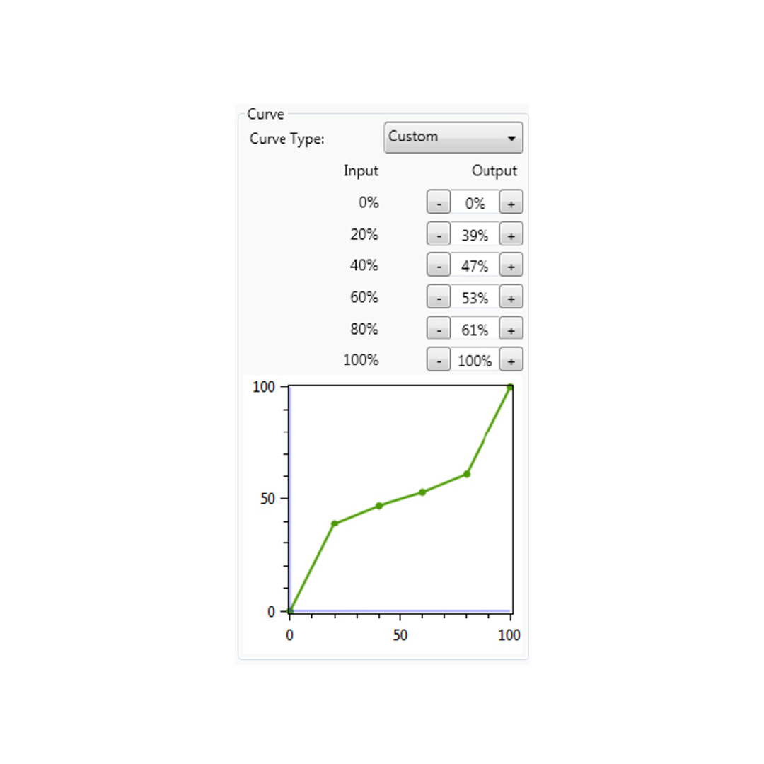 Use case 3 Clutch curve with optimal bite point setting
Use case 4: Early brake lock compensation
Some cars in certain titles are known to lock the wheels well before maximum brake input is reached, for example already at 70% of pedal input. SmartControl allows you to set a lower output percentage at 100% pedal input.
This means you can use the full force range of your brake (close to 100% pedal input instead of 70% pedal input) pedal before your wheels start locking up.
-
 Use case 4 Early brake lock compensation
Using SmartControl with iRacing
The Sim Pedals Sprint output values per pedal axis always range from 0-4095, regardless of your settings in SmartControl. Most simulator software can instantly use these output values, because Windows works with a default range of 0-4095 for 12bit USB devices as well.
A notable exception is iRacing, because iRacing uses an in-game method to calibrate the pedals. In order for the Sim Pedals Sprint to function correctly in iRacing, you must do the following:
- When using the pedal calibration wizard in iRacing, you will see a RAW value. When asked to press a pedal, make sure you always press it to a value of 4095 for every single pedal.
- Always set the Brake Force Factor to 0.
This ensures that your SmartControl settings always function correctly in iRacing. You will only need to calibrate in iRacing once. Re-calibration after changing SmartControl settings is not required.
iRacing offers the optional setting ‘custom controls for this car’. If you use this setting, always make sure to follow instructions 1 and 2 per car in order for your SmartControl adjustments to function correctly in iRacing.
Save a profile
SmartControl allows you to store an unlimited amount of profiles. In order to save a profile, do the following:
- Click File, then click Save Profile.
- Select a folder where you want to save your profiles.
- Set the desired filename, leave the extension (.xml) as is.
- Click Save.
Load an existing profile
In order to use a previously saved profile, do the following:
- Click File, then click Open Profile.
- Locate the profile, then click Open.
- In order to apply the profile, click Save settings to the pedals in the Profile tab.
Good to know
All profiles are saved relative to your personal calibration values. This means that you can exchange pedal profiles with fellow Sim Pedals Sprint owners and apply them without re-calibrating.
Profile changes are applied directly onto the Sim Pedals Sprint controller board. If your simulator software is Alt-TAB friendly, you can apply a different profile or test specific adjustments in the middle of a training session.
Mechanical adjustments
Next to SmartControl adjustments, there are also plenty of mechanical adjustments that change the feel or ergonomics of your Sim Pedals Ultimate+.
Overview
All pedals:
- Pedal angle
- Pedal plate height
- Hydraulic damping adjustment
Throttle & Clutch:
- Pedal travel
- Overall pedal force
- Pedal spring preload
Clutch only:
- Pedal force curve
Brake only:
- Pedal resistance
- Coil spring preload
Each of the adjustments will be explained in detail below.
All pedals – pedal angle
You have the option to adjust the pedal angle.
In the default configuration the pedals are slanted backwards 10 degrees. This is a useful position if your seat is relatively high compared to the pedal area, or if your rig has an angled base / pedal plate.
The lower your seat is relative to the pedal area, the further you may wish to angle your pedals forward. A total range of 15 degrees (from -10 degrees to +5 degrees) is available.
Adjusting the pedal angle is done by adjusting the angle of the pedal body relative to the rear feet. Do the following in order to adjust this angle:
- Using the 5mm hex key, remove the 2 bolts which sit in the small holes in the rear pedal feet (indicated in the image below). You can take out both bolts at once, the internals of the pedal will not be affected.
- Move the pedal up or down. Slightly loosen the 2 bolts in the front feet if the pedal is difficult to move.
- Insert the 2 bolts in the inner spacer and tighten both bolts.
All pedals – pedal plate height adjustment
The pedal plate of each pedal can be set in 3 positions in order to accommodate different lengths of human feet. By default the pedals are in their medium position. If you race without shoes and/or have small feet, you may benefit from a lower pedal height. The pedal height is adjusted as follows:
- Using the supplied 2,5mm torx key and 7mm wrench, remove the bolt and nut which hold the pedal plate.
- Remove and reposition the pedal plate. The hole for the bolt in the pedal plate should line up with 1 of the 3 holes in the pedal arm.
- Re-insert the bolt and nut and tighten.
All pedals – hydraulic damping adjustment
The dampers on each pedal can be adjusted in infinite steps, to change the strength of the hydraulic damping. By default, the dampers are in their medium position.
In the pedal arm, you will find an adjustment slider to change damper’s strength. In the top position, the damping effect will be at its strongest. In the bottom position, the damping will be at its lightest. It also slightly changes the overall amount of force required.
Please note that the throttle pedal uses a 1-way damper, it is only effective when you push the pedal, not when you release it. The dampers on the brake and clutch pedals have their effect when pushing the pedal and when releasing it.
The adjustment is made as follows:
- Loosen (do not remove) the bolts on the adjustment slider
- Slide the adjustment bolt to the desired position.
- Re-tighten the bolts.
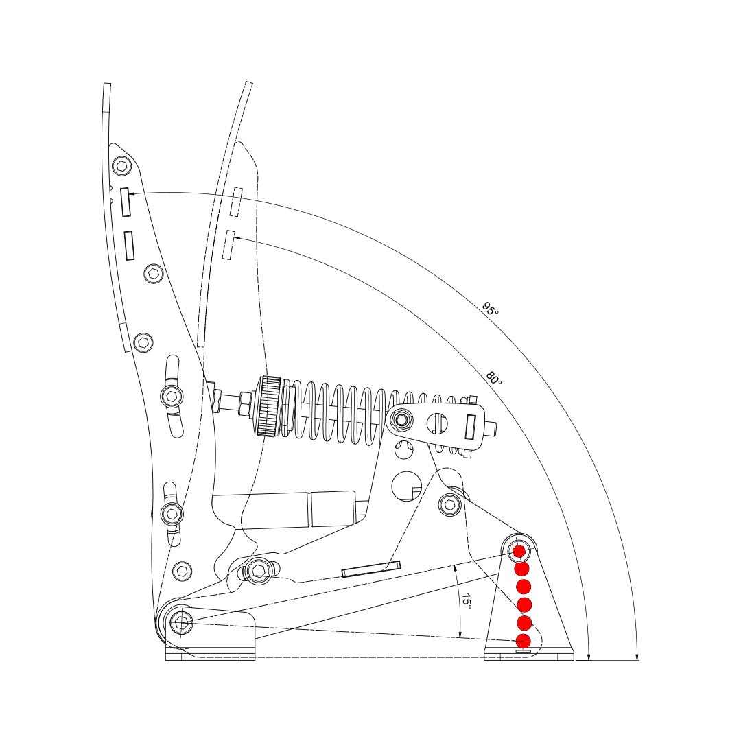
Throttle & Clutch – pedal travel
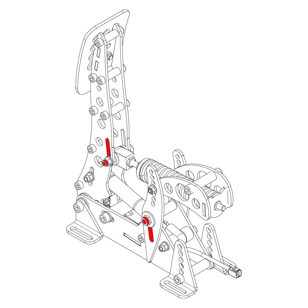
The pedal travel is limited by the blue end-stop which is located in the pedal base (indicated red in the image below). You can adjust the travel as follows:
- Using a 5mm hex key, loosen the bolts on each end of the blue end stop.
- Move the end-stop to the desired position. Then retighten the bolts.
- You must re-calibrate in SmartControl after adjusting the travel of the pedal.
After adjusting, verify that the metal coil spring does not bottom out when the pedal is fully pressed. If it bottoms out, adjust the pedal spring preload.
Throttle & Clutch – pedal spring preload
Next to the metal coil spring you will find an adjustment to change the spring preload (indicated blue in the image below). By making the spring length in the rest position shorter or longer, you change the initial amount of force required to move the pedal. The slope of the force curve will remain identical.
The adjustment is made as follows:
- Use the supplied 10mm wrench to remove the lock nut from the preload adjustment nut.
- Set the desired preload by turning the preload adjustment nut. Make sure that you don’t turn the preload adjustment nut beyond the thread of the rod.
- Tighten the lock nut back against the preload adjustment nut.
- Check if the other lock nut, which tightens the rod into the metal eye (inside the pedal arm), is still tight against the eye.
After adjusting, verify that the metal coil spring does not bottom out when the pedal is fully pressed. If it bottoms out, adjust the pedal spring preload.
Throttle only – pedal force
In the arm of the throttle pedal you’ll find an adjustment (slider) to (mainly) change the slope of the pedal force curve (indicated green in the image below). In the highest position, you’ll need more force to reach the end of pedal travel compared to the lowest setting. It also slightly raises the overall amount of force required.
The adjustment is made as follows:
- Loosen (do not remove) the bolts on the adjustment slider.
- Slide the adjustment bolt to the desired position.
- Re-tighten the bolts.
-
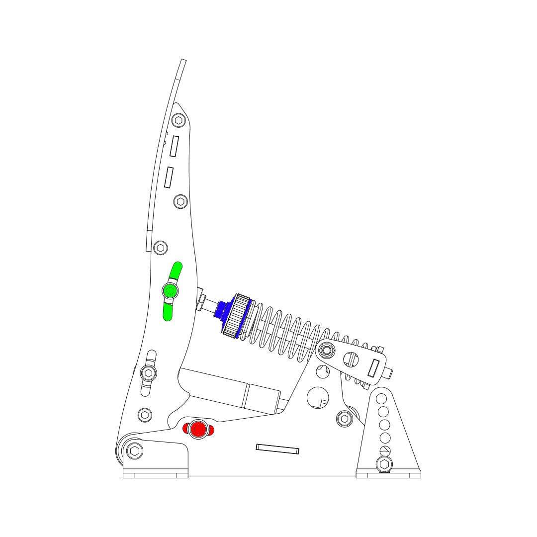 Travel adjustment (red), preload adjustment (blue), force adjustment (throttle only, green).
 -
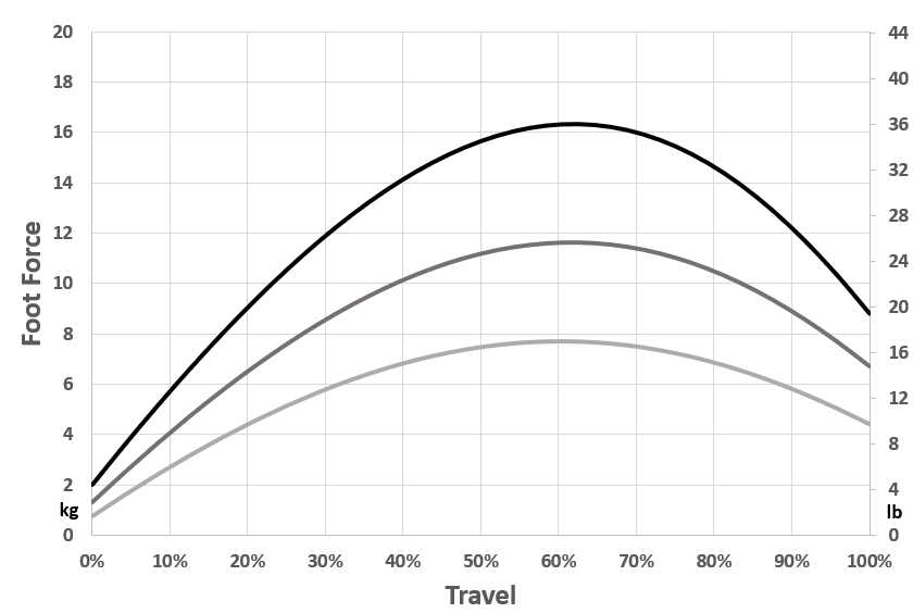
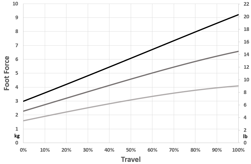 Minimum, average and maximum throttle curve.
Clutch only – pedal force
The procedure to adjust the clutch pedal force differs slightly from the procedure to change throttle pedal force. Instead of one slider you need to adjust two sliders.
In the moving front arm and in the rear (static) side arm of the clutch pedal you’ll find two adjustments (sliders, indicated in red in the image below) which mainly change the pedal force.
The adjustment is made as follows:
- Loosen (do not remove) the nut on the adjustment sliders.
- Slide the adjustment slider to the desired position.
- You must move the entire assembly up or down, not only the front or rear part of the assembly.
- For the lowest force, this means that the bolt in the front arm is in the lowest position in the slot, while the rear bolt is in the highest position in the slot.
- For the highest force, this means that the bolt in the front arm is in the highest position in the slot, while the rear bolt is in the lowest position in the slot.
- For a medium force, position both bolts in the middle. For every setting you choose, both sliders must sit in the opposite position in their relative slot.
- Re-tighten the nut.
-
 Clutch force adjustment slots.
 -
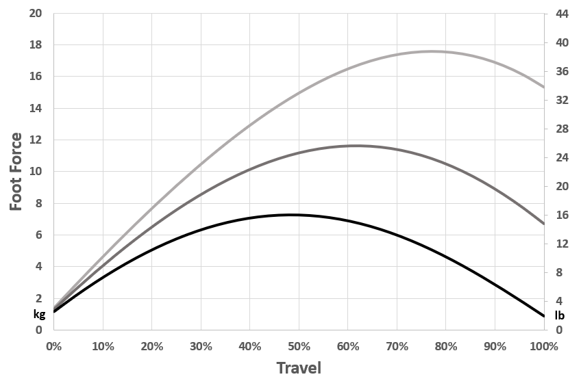 Minimum, average and maximum clutch force curve.
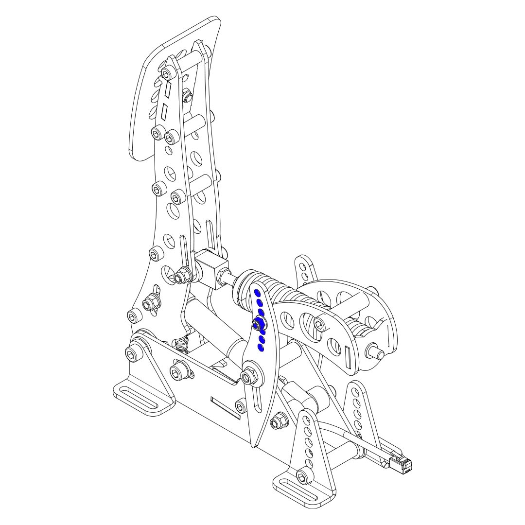
Clutch only – pedal force curve shape
At the rear of the clutch pedal arm is swing arm. This is the part which at the fronts pivots relative to the side arms, and at the rear holds the backplate which supports the metal coil spring. The exact position of this swingarm in one of the 7 holes determines the shape of the force curve.
You can adjust this curve as follows.
- Remove the metal coil spring assembly:
First remove all preload from the metal coil spring.
Then use a hex key to remove the 2 bolts in the slider in the front arm. Take note of the position of washers, spacers and bearings. Remove the eye joint with the axis connected to it and the spring. - Using a hex key and wrench, remove the bolt and nut which form the hinge of the swing arm. Note the washer which sits between the swing arm and the side arm, this should also be removed for now.
- Pick a new position for the swing arm (indicated in blue in the image below).
- Re-install the bolts and nuts which form the hinge.
- Re-install the metal coil spring assembly.
The top hole sets the most concave force curve. The bottom hole sets the flattest force curve. The following image shows the flattest concave, medium and most concave force curve.
-
Swing arm position adjustment.
-
 Maximum, minimum and average clutch pedal force curve shapes.
Brake – principle of operation
The Sim Pedals Ultimate+ brake pedal is force based. The harder you press, the higher the signal output to the simulator software will be. The force detection is lineair unless the output curve is modified in SmartControl.
Your brake is equipped with a 2-stage system. Initially a metal coil spring is compressed. This coil spring simulates the padto-disc gap. The main loading of the brake disc is simulated by compressing the rubbers.
By adjusting the brake pedal deadzone in SmartControl you have the option to let the brake signal output start as soon as you compress the metal coil spring, or only after the metal coil spring has been fully compressed.
Brake – pedal resistance
The Sim Pedals Ultimate+ allow for a large range of settings to set the resistance of your brake. This is done by varying the total length of the elastomers in the brake rubber stack and/ or the hardness of the elastomer.
Please note that adjusting the resistance determines how much pedal travel you will get for a fixed amount force applied to the brake pedal. The total amount of force required to get 100% pedal output in your simulator software is set in the SmartControl software.
A total of 9 resistance settings are available.
Possible settings with hard rubbers:
- 1x hard 19mm elastomer. This is the hardest setting. (A)
- 1x hard 28mm elastomer (B)
- 1x hard 37mm elastomer (C)
- 1x hard 19mm + 28mm = 47 elastomer (D)
- 1x hard 19mm + 37mm = 56mm (E)
- 1x hard 28mm + 37mm = 65 elastomer (F)
- 1x hard 19mm + 28mm + 37mm = 84 elastomer. This is the default setting (G)
Possible settings with soft rubbers:
- 1x soft 28mm + 37mm elastomer (X)
- 1x soft 19mm + 28mm + 37mm elastomer. This is the softest setting. (Y)
All rubbers are marked ‘hard’ or ‘soft’ on the side of the rubber. The hard elastomer can be used up to a load of 140kg. The soft elastomer can be used up to a load of 100kg.
Do not build rubber stacks other than the 9 options outlined above. Damage to the product may otherwise occur.
Do not mix hard and soft rubbers on one stack. We cannot accurately predict the resistance behavior of mixed stacks. Also, your stack will only be able to cope with the maximum force of the softest rubber in the stack.
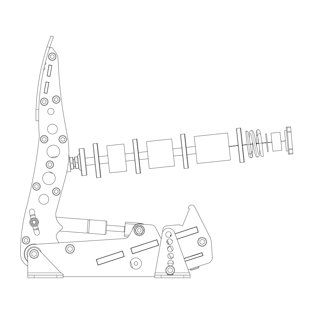
-
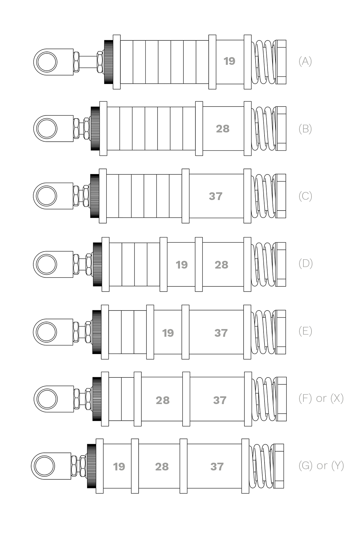 Possible brake rubber stacks.
 -
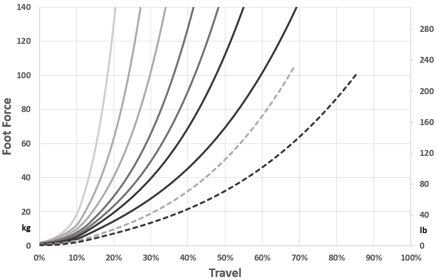 All possible resistance settings. Dotted lines are soft rubbers.
The brake pedal resistance is changed as follows:
- Remove all preload on the rubber stack. First you need to turn the lock nut towards the pedal arm, using the supplied wrench. Then you turn the black knurled adjustment nut towards the pedal arm.
- Pop the rubber stack out of position by pressing with 2 thumbs on the rear of the pedal backplate.
- Remove or add rubbers, discs and spacers as desired. Look carefully at the rubber stack schematics to correctly assemble a rubber stack. There must always be a large disc before and after every individual rubber.
- Pop the rubber stack back in position.
- Re-set the desired preload by turning the knurled nut. Make sure there is enough tension on the rubber stack so it won’t pop out. Do not turn the preload adjustment nut beyond the thread of the rod. If this happens, consider adding an extra spacer.
- Lock the knurled nut by tightening the lock nut firmly against it.
- Recalibrate the pedals in SmartControl.
-
 Rubber stack popped out of position.
 -
 Rubber stack schematic.
Maintenance
Your Sim Pedals Ultimate+ have been designed to have a minimum of wear, tear and noise. In order to keep your pedals in good shape for many years, we recommend following these maintenance procedures.
Preventive lubrication – throttle & clutch
Most pivot points on the Sim Pedals Sprint have self lubricating bearings. On the throttle and the clutch there are 3 positions which may however receive preventive lubrication:
- Bearing in the backplate (rear part of the swingarm, through which the spring rod runs).
- Both side-bearings of the swingarms.
Please refer to the images on the next page to see the exact location.
The recommended lubricant for the throttle and clutch is PTFE Dry Spray. A good service interval would be to lubricate every 100 hours of use.
Lubrication – brake pedal
Lubrication of the brake is only required if the brake makes an unwanted noise. In this case, check if the noise comes from the bearing in the backplate of the brake (through which the rod runs). If so, apply a bit of lubricant to this bearing. The recommended lubricant for your brake pedal is PTFE Dry Spray.
Safety
Please take note of the following when using our pedals.
General product description and intended use.
The Sim Pedals Ultimate+ is a sensor-based pedal set which can be connected to a computer for use in a driving simulator. The product is suitable for use in a simulator only. The product is not suitable for use on (public) roads, on a test track, or as part of an electric vehicle.
Safety precautions
No specific personal safety equipment is required to use this product. We recommend considering wearing shoes when using the product. The product must be mounted rigidly to the simulator. When driving, the seat of the simulator and the product must not be allowed to move freely relative to eachother.
Recycling
We try to make our products as durable as possible. Please act responsibly when you need to discard (parts of) this Heusinkveld product.
The packaging of the Sim Handbrake is made out of paper and cardboard where possible. Please use the appropriate paper waste stream to dispose the packaging in case you don’t want to keep it.
At Heusinkveld we support our products with spare parts for many years after the original production date. In the very unlikely case the product itself needs to be scrapped, please make sure to follow local guidelines for responsible recycling.
If you need to disassemble the product, please use the provided tools to do so. This allows you to separate the various materials used in the product.
If you are unsure how to responsibly recycle the product, you may always send it back by mail to Heusinkveld.
Our mail address is:
Heusinkveld Engineering
Cuxhavenweg 5E
9723JK Groningen
The Netherlands
CE Declaration of Conformity
You can download the CE Declaration of Conformity here.